Building a Dummy Load
and
Measuring Power Accurately
by Ken, K4EAA
|
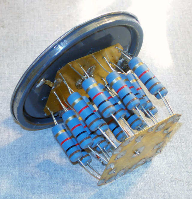
Building the Dummy Load This is a take-off on a Dummy load that I've built in many different forms over the years. It uses a number of non-inductive resistors in parallel to achieve 50 Ohms over a wide frequency range. It is submerged in oil to allow somewhat extended operation during tuning or repair procedures. The advantages are: (1) It's cheap, (2) It provides a very pure 50 Ohm resistive load through 30MHz and beyond, (3) You can easily add power measurement and rig testing capability. This one is conservatively designed for rigs that have power output levels up to 130W, such as the Kenwood hybrid lineup. I built it into a one-quart paint can, readily available at Ace Hardware for about 89 cents. I've used it for about a year now. A few hundred of your service rigs that you have sent to me have been loaded up into this dummy, and it is still like the day it was built. I know, because I had to take it apart to take these photos! It still measures 49.9 Ohms, even after all those rigs, all that power! Note: The normal failure mode for resistors is to go UP in resistance value. If you think you have "fried your dummy," check it's resistance value - If it is much higher than 50 ohms, you have successfully cooked it. This dummy load will be very hard to destroy. The parts required to build it are the Ace Hardware one-quart paint can or similar, twenty 1K 3W metal film or metal oxide resistors, a small brass sheet, also available at Ace, and an SO-239 connector, preferably single hole mount. Mine was built with a BNC connector, because all my home-brew rigs use BNC, but you'd probably find it more convenient using the SO-239, for your PL-259 plugs. To add the optional power measurement capability, you'll also need a pair of red and black banana jacks or binding posts, and a BAV21 signal diode or similar, 7 cents quantity one at Mouser. Construction Details Drill a hole in the center of the paint can lid that will accomodate your connector. Cut out two pieces of brass sheet using tin snips to a size that will easily fit into the paint can. It's quick to just cut two squares and the snip the corners off, forming an approximation of an octagon. Stack these brass octagon sheets and drill 20 holes staggered around the periphery. Nothing is critical, you simply want to keep the resistors spaced apart a bit in the oil bath. After drilling the brass sheets, including a hole for your SO-239 connector in the center at the top, and a small hole for the lead for the center conductor on the bottom sheet, you can solder the resistors in place. Note on easy assembly - Solder all 20 resistors to one plate, and then, starting at one corner, and working toward the opposite corner, cut the lead lengths starting from your minimum length, to progressively longer as you work towards the opposite corner. This will allow you to insert a few leads at a time as you combine the two plates. If they are all the same length, it will be very hard indeed to thread the 20 resistor leads into the bottom plate! You can find the resistor kit for sale HERE Here is a photo of a completed assembly connected to the paint can lid. |
|
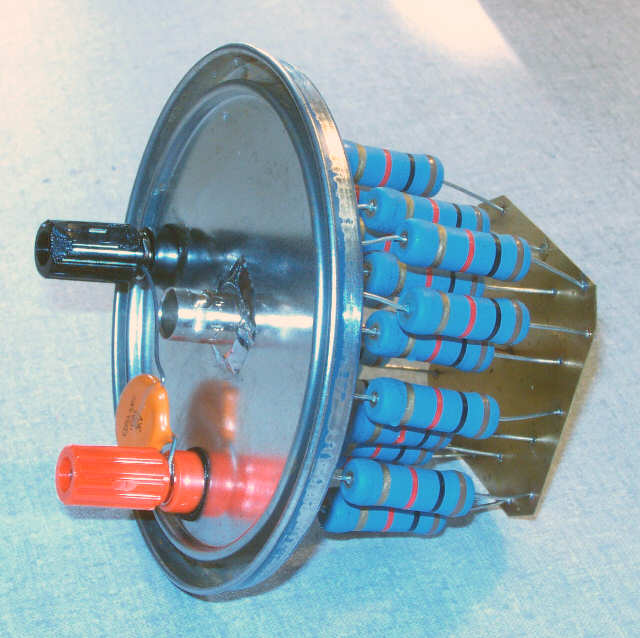
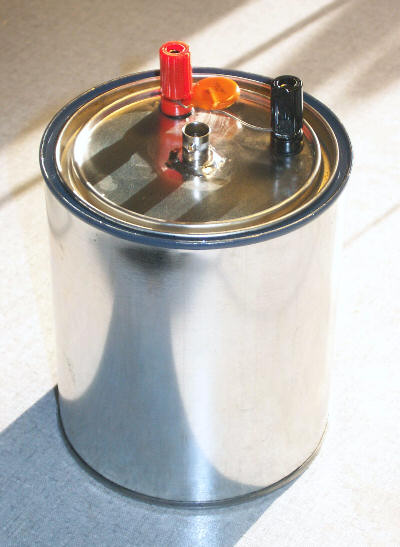
Here is another picture of the assembly, showing the connector and the optional binding posts. I used a BNC connector, but you probably want to use an SO-239. |
|
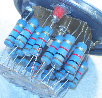
For those of you that wish to add power monitoring capabilities, you have to add two binding posts by drilling two additional holes, and mounting the posts. The following picture shows two 1N4148 signal diodes wired in series from the center conductor to the red binding post. I recommend the BAV21 250V signal diode. I used the two 1N4148's after checking their reverse breakdown, because I had lots of them. The "goop" around the base of the binding posts is some silicone bathroom caulk added to keep the oil from weeping through the mounts. The black binding post simply attaches to ground. |
|
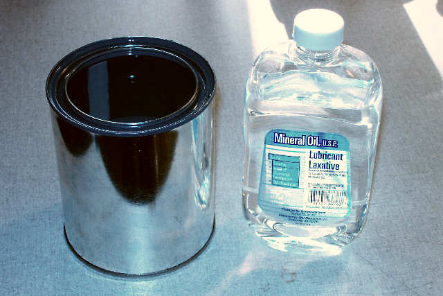
Next, we fill the quart paint can with mineral oil, which is a safe (You can actually drink it! - No PCB's for our dummy!), inexpensive, and readily available. The mineral oil works very well for conducting heat away from our resistors - It enables us to use 60W worth of resistors safely with a 130W rig. |
|
Lastly, we complete assembly by attaching the lid to the mineral-oil filled paint can. |
|
Now we'll find out how to use the optional diodes and binding posts that we've included in the dummy load.. Measuring Power Accurately The signal from your transmitter or transceiver is an almost perfect sine wave. We know this because the harmonics are at least 40 dB down from the carrier. When we measure the peak voltage from the detector (the BAV21), we are measuring within one percent of the true peak value of our carrier, not including the diode drop; we will add that back in later. For power measurements, I recommend that a 0.01uf disk ceramic of at least 250V rating be connected between the binding posts. This will charge to the peak voltage applied to the 50-Ohm load, less the diode drop. You can then measure this voltage with your DVM. Let's assume you measure 99.6V with your DVM. Add 0.4V for the forward drop across the BAV21 for a total peak voltage reading of 100V. The diode drop is a constant, always add 0.4V to your reading! (This assumes you are using a DVM or scope with an input impedance of 10 Megohms. For 100V DC, the forward current will be 10ua, for a forward drop of 0.4V) Since this is a peak voltage, we need to divide by the square root of two to get RMS voltage. Take your calculator and divide by 1.414. 100 divided by 1.414 equals 70.72 Vrms. To calculate power, we take the RMS voltage, square it, and divide by the load impedance, which in our case is ALWAYS 50 Ohms! (70.72)^2 / 50 = 100W So the output power, dependant on the accuracy of your DVM, is nearly 100W. If your DVM is accurate, say within 1% on DC voltage measurements, you have nailed your rig's output power within 2%, or 2W! That's good. Consider a Bird Wattmeter. Their specified accuracy, when new & calibrated, is 5.0% of full-scale when the measurement is at 1/2 scale. So, for example, a 200W element used to measure the 100W output of your rig can fall within 10W, so your 100W rig might measure 90w to 110W and still be within the calibrated accuracy specification. That's 20W of ambiguity. On the other hand, when power is measured by looking at the peak voltage, accuracy is a function of your DVM accuracy, plus the distortion in your output signal, the total of which may be on the order of 2% - - That's a 98W to 102W measurement, substantially more accurate! One More Time We'll do this once more, just for drill. Assume you measure 49.6V across the 0.01uf capacitor. Add 0.4V for the diode drop, for a total of 50V peak. Divide by the square root of 2, or approx. 1.414. That gives us about 35.4Vrms. Square and divide by 50 Ohms, and we get 25W. Half the voltage, one-fourth the power. If you place your power meter inline while you are taking this measurement, you can then calibrate it to your calculated power output measurement. I use these measurements, together with a calibrated Fluke DVM, to calibrate my power meters, and then I know my power measurements into my dummy load, or any 50 Ohm resistive load, are quite accurate. |
|
Other Measurements Once you have the rectified output signal available from your dummy load, you can make other measurements. By selecting a filter capacitor and a parallel resistor across your binding posts to tailor your time constant, you can check the CW keying waveform across your binding posts, for instance. Here is the schematic for the load. |
 |
 |
 |
 |
 |
 |
 |
Please Note: The above address is a
GIF image, to foil spammer robots.
You will have to type that address into your email client. Thanks
for your understanding, Ken.
All Photos and content copyright 2018, 2006 K4EAA, Ken
Kemski.