|
Welcome to the K4EAA Kenwood hybrid FAQ. Here is where I'll try to answer your questions that have not been addressed elsewhere on my site. Please feel free to email with questions you might have. I'll do my best to try to post answers for them here. Please
use the FIND command in
your browser to quickly search for topics of interest on this page. What is the difference between a TS-830S and a TS-830S "Gold Edition" or "Gold Label?" At some point Kenwood introduced the "Gold" version of the 830S. It came from the factory with all four filters installed, 2 for CW and 2 for SSB. The 830S had a VBT control, which required overlapping of the 2 sets of filters, by varying the heterodyne frequencies, to achieve a variable bandpass. The standard 830S had only the 2 SSB filters factory installed, with the CW filters optional. The VBT with the standard filters varied the bandpass from about 800Hz to 2.4KHz. Adding either CW filter will allow a 500Hz CW bandwidth, but the inclusion of BOTH filters allowed the VBT to adjust from 0 to 500Hz BW - A very nice improvement. The "Gold" series came with all 4 filters installed. Be advised that many Gold 830S's today have had their CW filters removed and sold separately.. UPDATE: I continue to occasionally hear from people that dispute the Gold/Full-Filter statement. After looking at over 100 TS-830S's I still have yet to find a Gold that didn't either have the filters installed, or show positive signs of filter removal. This issue will probably remain in limbo, however, until someone finds a brochure or sales flyer touting this "Full Boat" transceiver. People have seen them, bought 830's as a consequence, but no one has any real proof. BREAKING NEWS: Joe Kenwood called me yesterday from Tokyo Japan, and confirmed that "Golds" were delivered with all 4 filters factory installed. This should put to rest any controversy, and prove my point once and for all! Thanks, Joe! 8^D Since Kenwood used insulated couplers for all of their hybrid models, why do you and many others recommend the use of solid brass couplers on the bandswitch? Shouldn't they be insulated? Because it's much stronger, and perfectly safe. If you examine the Kenwood 830S final cage, for example, you'll see that two of the three shafts are solidly grounded at the RF cage itself. The bandswitch frame, bushing, and shaft are directly connected (bolted) to the chassis of the radio. The load control is mounted solidly to the chassis, with the capacitor frame and shaft screwed right to the chassis at RF ground potential. The tuning shaft on the plate capacitor has an insulated, phenolic shaft going to the coupler. Since I've never seen a broken coupler on this shaft because of the low torque it sees, there is no reason to change out this coupler anyway. Keep in mind that the front panel knobs are insulated as well. What is the difference between a TS-520S and a TS-520SE? In an era of intense competition between Kenwood and Yaesu, to name a few, the use of the "Sears-Roebuck" Good, Better, Best marketing philosophy was put to good use. Yaesu introduced the FT-101E, or "Economy" model, so Kenwood had to counter with the TS-520SE, "Economy" model. The 520SE eliminated the plug-in line cord and optional DC converter, as well as the filament (heater) switch. I can't imagine they saved a lot by removing a switch, or the provision for the optional DC converter, but it was a marketing decision. Otherwise the 520S and 520SE are identical. Then where does the TS-520SP fit in? Kenwood was on the verge of bigger and
better things, namely their 530S and 830S lines. The 520SP
included Kenwood's first NOTCH
filter, which allowed operators to tune out an annoying heterodyne, or
some of an offending nearby SSB station. The 520SP is a 520S with
an added notch filter. Can I use Acid -core solder to repair my Kenwood? Sure, if you'd like to watch the flux migrate around your boards, and carbonize and smoke when you turn the rig on! Acid-core solder is a large no-no, I thought everybody knew that by now. I just recieved a rig that smoked a lot when keyed, no output power, and guess what? Yup, conductive flux everywhere on the RF board. That stuff wicks and spreads everywhere! How do you clean it? Well, there's only one way. Hold onto your seats, those of weak heart, and observe this RF board being cleaned. I do this occasionally for otherwise filthy boards, I just don't tell Hams that might not understand the beauty of it all . . . To paraphrase an ancient TV commercial: "Marsha - Is Palmolive liquid safe for electronics?" Marsha looks her squarely in the eye. "Your RF board is soaking in it" she says. 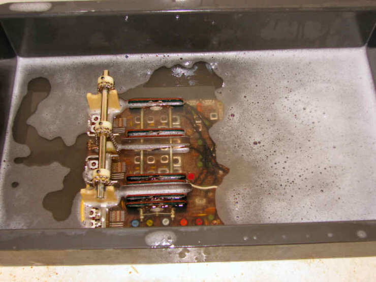 The cleanest board in the radio now makes its reappearance after being scrubbed, rinsed, blown with compressed air and allowed to really dry out over a day or so. The contacts, ALL contacts, were cleaned and lubed thoroughly as well. Remember to re-grease the shaft, also. 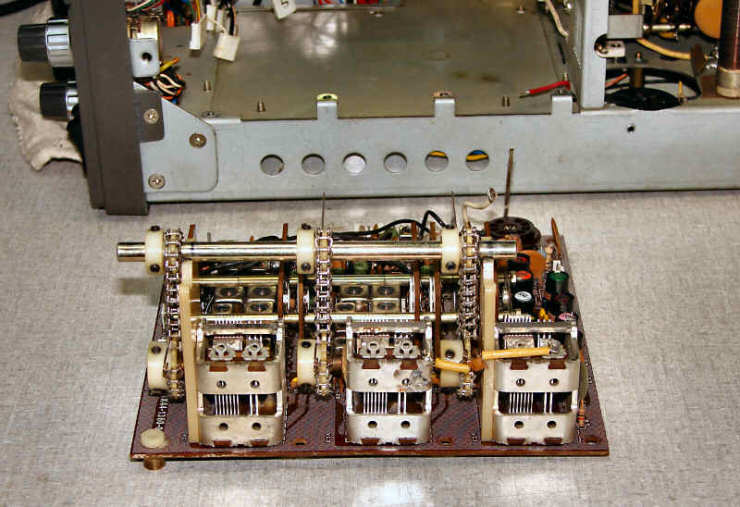 It worked sublimely after the major cleanup . . . And, it looked new! One of my friends has a 520D. What the heck is THAT? I think I have one of those also - Buried in my stash of Kenwood radios . . . The 520D was a non-export, Japanese market radio. Obviously, a number have made it to the U.S. over the years. The only caution here is to make sure it's wired for 120VAC operation, because the factory defaulted to 100VAC for use in Japan. I see that there are QRO mods for the Kenwood hybrids, designed to pump their output power up to 150W or more. Is that a good idea? I'm not in favor of increasing the power
output of the Kenwood hybrid series. One of the reasons these
rigs have survived to this point, and that you are reading this FAQ, is
that Kenwood designed them conservatively. They could have
squeezed out more power, but opted for a long, reliable life
instead. Besides, the difference between 100W and 150W output is
hardly worth anything - It amounts to 1.7db, and an S-unit is 6db -
What, a needle width at the other guy's receiver, at the expense of
shortening the life of your power supply, final tubes and related parts? I think my receiver in my Kenwood needs alignment. Is there a quick way to check the overall condition of the receiver? Kenwood provided a pretty nice 25KHz calibrator in all of the models. It improved with time, but even the first TS-520 provided a usable test signal. On most Kenwoods in good, original condition, where the internals haven't been tampered with too severely, on 20M the calbrator should measure S-9, or close to it. Set your receive frequency to 14.175MHz, peak your DRIVE control, and look at the S-Meter. If it reads S-9, your alignment may be OK. On most rigs (Remember they are 20 to 35 years old), I can achieve about 1-2 S-Units of improvement during the alignment, many more if the unit has been subjected to mobile or field-day abuses. Keep in mind that a previous owner may have simply cranked up the S-Meter pot, throwing off your measurement, but if it's YOUR rig, you can accurately asses it this way. I have hum on my SSB signal. Several stations have complained about it, should I send my rig to you? Before you send it off for repair, a simple check might solve your problem. Kenwood used separate grounds on the MIC connector for the PTT switch, and the microphone signal and ground leads. If your microphone is mis-wired, and I have seen a number that are, you will get hum on your signal. Kenwood stresses in their owner's manuals, "KEEP THE GROUNDS SEPARATE" but some people have to learn the hard way. If pins 3 and 4 on your microphone connector (on the microphone cord itself) are connected, you will have hum. When I switch my Meter to RF, it reads low (high, or not at all). What should it read? The RF position of the METER switch is a relative indication, that depends on where the RF pot has been set by you, or someone before you. Kenwood included it as a means of peaking your forward power, if you didn't have an inline power or SWR meter. In early hybrids, the adjustment was inside the side panel door, along with the VOX controls. On later hybrids, it's on the back panel. When your rig is operating normally, after you have tuned into a dummy load, you simply adjust the RF control until the meter reads about 2/3 to 3/4 of full scale. You then use it as a relative reference for forward power, much as you would use a power meter. I've read where certain resistors in the hybrids served double-duty as fuses. What gives? Usually the resistors, if you overload your rig for extended periods! <g> As I've told lots of other people, the first thing I check when I unbutton a rig is the cathode and screen resistors. That gives me an immediate indication of whether the rig has seen some abuse during tune-up or operation. Kenwood made the cathode and screen resistors in the final section just large enough to do their job, with a little room for beginning operators learning to tune it up properly. Before any real damage can occur to the expensive items, like the power transformer (priced one lately at kenwoodparts.com?) or the final tubes, the cheap resistors will give it up. Cheap, simple, and quick to replace, they have saved many, many Kenwood hybrids from the bone-pile. See my further description HERE. How can I tell when my cathode resistors are cooked? The easiest way is to measure them, with a zero-adjusted ohm-meter. From cathode to ground, it should read 5 Ohms, +/- 5% (4.75 to 5.25 Ohms). You can see tell-tale signs without opening the case, however. The plate current metering is read from the cathode voltage, and the higher the cathode resistance, the higher the plate current reading. Also, the lower the output power. If you read high plate current and low output power, those cathode resistors are probably climbing in value! The plate current is actually lower than what you are seeing, and the output power is just confirming it. Time to order some replacement resistors! How do I know when I have bad final screen resistors? The final screen voltage directly affects your output power. It is the basis of most QRO mods, just raise the screen voltage beyond the Kenwood design values, and viola! More power!. Since we already know we probably don't want to RAISE the screen voltage, what we are concerned with here is too LOW of a screen voltage. Again, the failure mode of resistors is to go UP in value when they are getting cooked, and that will also lower the screen voltage in the Kenwoods. If your fresh finals are not providing an honest 100W output, and if you have plenty of drive, it's probably a good time to check your screen voltage, and the value of the 100 Ohm and 470 Ohm resitors in series with the screens. There can be other causes, but let's go with the most common, and check those resistors first. How can I tell when my finals (6146's) are getting "soft?" Tubes go "soft" when their cathode emissions begin to drop. That means that for a given set of circumstances, plate voltage, screen voltage, drive level, etc., fewer electrons make it from the cathode to the plate. When this happens, plate current begins to fall off, output power starts to drop, and we start to increase the LOAD control and re-dip to maintain the power output. As we increase the LOAD control, and more heavily tax the finals, the tuning starts to get broad, with a much less pronounced "dip." This can occur gradually over time, so we tend to overlook it. Finally, we're seeing 70W out on 20M with very broad plate tuning - It's time to replace the finals. Fortunately, for Kenwood, this can take over 35 years, depending on your operating habits, as I get lots of rigs with the original S2001 tubes in place, almost as good as new! When should I replace my 12BY7A driver tube? The ALC metering directly measures the performance of your driver tube. Usually, when the tube starts to go soft, it will be hard to obtain full ALC swing on the highest bands. 10M will always go first. As long as you have sufficient drive to get well into the ALC range on the bands that you work, the tube is fine. When ALC drops to zero on bands of interest, it's time to replace it. You need ALC indication for the speech processing and other features to work properly, so don't operate in the grey areas ouside of normal ALC readings. What makes ALC work? What is the meter reading actually showing me? Kenwood sort of borrowed from Collins here, their circuit looks to see if any final grid current is being drawn, and lowers the drive as required to keep final grid current near zero. About 200na (yes, that's nano-amps) will move the ALC reading into positive territory. As soon as grid current is drawn, however slight, the ALC amplifier will reduce the drive to the finals via the IF board. This keeps the output clean, and prevents the finals from being overdriven. Where can I get the proper metric screws for my case fastenings? Surprisingly, you can get Kenwood replacement screws at your local Ace Hardware. My Ace has them in small bins, and I ordered a few boxes of 100 for the two different sizes for replacement use. I'm always surprised when I get rigs with (i.e.) drywall screws or something holding them together, when nice metric fasteners are available almost everywhere! In your Tune-Up procedure, you intimate that 225ma is a sort of "Magic Number" for plate current. Why is that? When we're adjusting the plate and load controls during tune-up, what we're actually doing is attempting to match the output impedance of the finals (the two 6146B's in parallel) to the 50 ohm load. Maximum power transfer always occurs when we match source and load impedance, and for a pair of 6146's in good condition, with nominal plate and screen voltages as found in the Kenwoods, that turns out to happen at around 225ma indicated plate current. 800VDC X 225ma also turns out to be 180W DC input, right at Kenwood's design goal. If you watch your output power as you increase loading while re-dipping, you'll see increasing output power until Ip reaches about 225ma, then it starts to come down again. Plate current will be higher, but power out will be lower. I think my antenna relay needs replacement or cleaning. Is there a simple test? On most of the hybrids, the antenna relays can be easily cleaned, and even adjusted if necessary. The 530S has proven not so repairable, and the bad ones I found had to be replaced. On all the others, a cleaning usually restores proper operation. To test the relay, open the case and tap the metal relay enclosure smartly with a small screwdriver handle while in "live" receive mode (Don't use the calibrator, as it's located after the relay). Static will tell you if the contacts are dirty. A clean, properly working relay will produce no sound in the speaker when tapped. One in need of cleaning will make noise, and perhaps even received signal strength will change on the S-meter every time you tap. I've seen it recommended to replace the doubly balanced mixer diodes in the Kenwoods with modern Schottly devices. Is this a worthwhile upgrade? Probably not. Here is the ultimate test: Turn off your AGC. Switch your receive antenna to the dummy load (or disconnect your antenna, preferably replacing it with a 50 ohm resistor). What you hear is the noise generated by the receiver in your Kenwood. Now reconnect your antenna. The much increased noise level is band noise, atmospherics, electrical noise, the stuff that is always there. Notice that it is much louder than pure receiver noise. No matter what you do, you will never be able to get any quieter than that. Plus, the Kenwoods out-of-the-box have at least as good a signal-to-noise ratio for a 0.25uv signal as most anything ever made, right up to the present. If it ain't broke . . . etc. Can I run PSK at full power output (i.e., 100W)? That is not a good idea. CW and SSB are low duty-cycle modes, while the digital modes are essentially 100% duty cycle. I would shoot for about 110ma absolute maximum plate current, that's about 90W DC input, 50W output, leaving 40W to dissipate in the tubes. You wouldn't want to push them any harder than that. Here, lower is better, as many PSK operators are running only 5W. Is it a good idea to replace the old 2-wire line cords on our rigs with modern 3 wire grounded cords? Surprisingly, no. In fact, many electrical codes around the country would frown on it. The reason is that they expect the ONLY ground on the house wiring to exist at the service entrance. Adding additional grounds at points perhaps on the other side of the house could produce ground loops, unexpected ground current flows, and unpredictable ground potentials. Because your Amateur equipment has its own ground system (or SHOULD), they do not want you to connect it to the primary service ground. Stick with a 2-wire line cord and the best local ground system you can attach to your gear. How can I Neutralize my Finals? Neutralization is the process of compensating for the inter-electrode capacitance of the final tubes. It helps prevent the tubes from oscillating, and allows them to perform as a stable amplifier. Here is a simple sequence for neutralizing your finals: (1) Tune up normally into a dummy load on 10M, perhaps 28.1 MHz (2) Turn your SG (Screen Grid voltage) switch OFF. This effectively turns off your finals, and will prevent them from putting any power into your measurement setup. (3) If your dummy load has external connections to monitor the RF it is seeing, use those - Otherwise, remove the dummy load and replace it with a 50 ohm resistor (47 or 51 Ohms, 1/2W will work fine) that is mounted onto a PL-259 Plug. During neutralization there is no significant power in the load, so use what's handy. (4) Using an RF millivoltmeter or oscilloscope with at least 20MHz bandwidth, connect it across the small 50 Ohm test load. A 20MHz scope will display 28 MHz adequately, although it won't accurately measure the RF voltage present. That's OK, because when we neutralize, we're simply tuning for minimum output. (5) Key the rig and observe the output voltage on your RF VTVM or Scope. This is the drive power "leaking through" to the load with the finals inoperative. Our goal here is to minimize this leakage, and in doing so, we will ne "neutralizing" the inter-electrode capacitance. (6) Using an INSULATED tool, either plastic or a carved wooden dowel, tune the neutralization capacitor for minimum output. You should be able to get down to 10 millivolts or so. There is LOTS of voltage present, so don't even THINK about using a metallic tool!! You will spark and arc and create all manner of scarey fireworks if you do - Not to mention perhaps joining the ranks of the SK's . . . Don't forget to return your SG switch to ON for normal operation. Why Can't I Successfully Neutralize my 6146A's? The Kenwood's were designed around the 6146B, which was significantly different from previous 6146 and 6146A versions. You should not use the 6146, 6146A, or 6146W built before the mid-1960's in the Kenwoods. After the 6146B was introduced in 1964, the 6146W's gradually were migrated to the 6146B design, and later versions of those tubes are fine. The neutralization circuit employed in the Kenwood hybrids was designed around the 6146B, and may not be able to successfully neutralize the older versions - That can lead to instability in the finals. Are Modern Resistors and Capacitors Really That Small? Electronic Components are shrinking as we speak. The last order of 0.01uf 1KV capacitors I received look more like older 100V disk ceramics. It seems to be occurring rapidly as many manufacturers are switching to RoHs compliant parts (no lead) to meet federal guidelines. As they phase out the old equipment and designs, they seem to be concurrently introducing new designs that take advantage of the improvements in modern materials and processes. These new designs are much smaller than their previous parts. The old lead-solder based parts are being obsoleted, and many are simply no longer available.
Can the new RoHs parts be soldered with my old soldering iron and lead-alloy solder? Yes. The leads on new parts for the most part are coated with pure tin, which solders normally. Just make sure you buy some old-fashioned solder before IT goes away!
What should I do after changing Finals? Whenever you change finals, you must read and understand the following information whether they are NOS U.S. or of foreign manufacture. Absolutely every time you change the finals in your Kenwood, you MUST do two things: (1) You must adjust the bias for the new tubes, and (2) you MUST neutralize the new tubes. Simple stuff, but you have to take these two steps to avoid problems. Whenever you install new finals, the following steps for adjusting the bias MUST be followed. Install the new tubes. Turn the bias pot full CCW (No bias). Turn on the rig and heaters. Turn your MIC control full CCW (no gain). Set your BAND to 14 MHz (20M). Set your MODE control to USB. Flip the SEND switch to TRANSMIT and adjust your bias for 50 ma. Why is this important? All tubes from different manufacturers or eras show differences in operating characteristics. You have to tune the factory provided adjustments to compensate for these changes when you swap finals. It may take a few minutes, but it is well worth the effort. Your new tubes will be operating safely, and will then provide many years of peak performance. For neutralization, see the FAQ question a few steps above this question. Do You Have Some Hints for Troubleshooting AGC and ALC Problems? In the past few months I have received a number of questions from owners with either ALC or AGC problems, and when they described what they were seeing and doing, it became apparent that they did not quite understand what was going on, and what they were seeing. The concept that what we see on the meter directly indicates the strength of the received or drive signals to the Tx is there for the end user, not the repair technician. If you are troubleshooting your own rig, you are the repair technician! What the meter actually shows is the level of the gain control signal that is being applied to the gain controlled stages to keep that signal at a needed value. This is an important difference. Let's briefly look at the transmitter side, and the ALC indication. In all the Kenwood hybrids, we have a generator that provides CW, USB or LSB signals. These are gain controlled stages, that is, the amount of the signal they provide is determined by a voltage appled to the dual gate MOSFETS that make up most of the circuitry of interest. It is a simple servo system, that is, when the signal out, in this case drive, reaches a certain level, a DC voltage is generated that reduces the gain in the Generator stages, keeping the signal output level at the predetermined value. The meter and its corresponding amplifier show this "gain control" signal, and shows how much gain reduction is required to keep the drive at its required value. To help visualize, recall what happens when you peak the DRIVE control while monitoring ALC in SEND mode - The meter peaks when you have the DRIVE control adjusted to resonance. This is because the ALC circuitry has to send a larger "gain reduction" signal back to the generator to keep the grid current in the finals near zero - The ALC is monitoring that grid current. While the meter is on scale, the output remains essentially fixed, with an error of 1/servo_gain, which is quite small. How can this help me fix the radio? Remembering that the meter is essentially functioning as a "log" amplifier, because the gain curves vs. control voltage are non-linear, mostly log in nature. When you have marginal gain in either the transmit or receive chain, the ALC or AGC will try to correct for that - But when conditions are near the minimums, your meter will tank when the stages run out of gain, that is, the meter gets close to zero in either condition. This is exacerbated by the logarithmic nature of the system. Readings look exaggerated with large swings when the gain stages can't keep up. Problems that are made harder to troubleshoot by these phenomena include loss of ALC when dipping the plate of the finals, and seemingly non-linear operation of the S-meter, especially if someone has tweaked the zero and sensitivity pots on the meter amplifier. It looks like everything is OK except for the anamolous operation of the meter. These problems can usually be eliminated by ensuring the gain of the Tx and Rx chain are really where they belong. Do I have to perform any alignment after changing the driver tube? Replacing the driver tube changes tuning enough that the rig
can usually benefit from a realignment of the RF board. Different
tube capacitances will shift the tuning on the Rx mixer and Tx driver
stages. It's usually not severe , and in worst case you will notice
that the DRIVE peaking on receive doesn't match the DRIVE tuning for
maximum ALC. A realignment will correct that, and line up the
receiver preselector with the transmitter drive peaking once again.
My MC-50 isn't working with my Kenwood. Should I send it to you for repair? Before you send it off, check out my Download Page , download the MC-50 instruction sheet, and read about how to insert the plugs into the MC-50 and stand. The two plugs will each go in 2 ways, for four possible combinations - Usually, only one of the four will work properly! If you don't look closely, you may not notice the red dots and the little "H" on the connectors. I'm having trouble aligning the
speech processor on my TS-820S. Are there any tricks to the
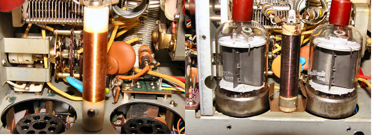
alignment procedure? My 530S (or 830S) receive
is very weak (or dead) on all bands - Even the calibrator signal is
very weak. I have determined that the problem is in the RF
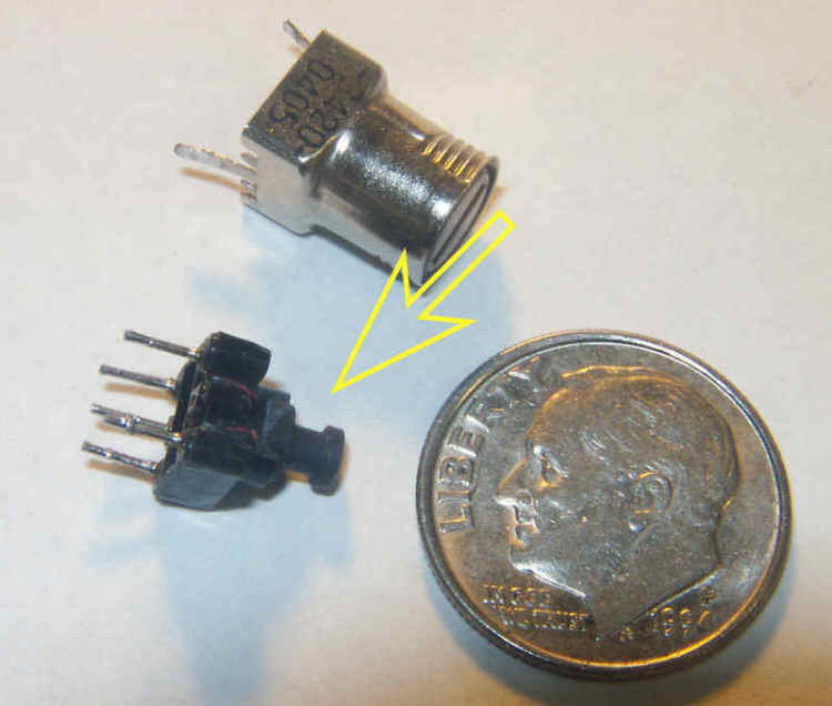
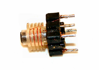
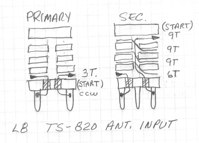
stage. Should I replace Q1, the RF amp MOSFET? The Wire size used is #42 enameled copper
wire. The primary is 6 turns, and the secondary is 26
turns. If you work under high magnification with a steady hand,
it is not difficult, or critical. Don't scramble-wind it, try to
make a multi-layer solenoid, but if a few turns are out of place, it
really doesn't make any difference. If Kenwood hybrids can be
damaged by mistuning, why didn't they place a bright red page at the
front of the owner's manual to warn us?? I have a 520 (530, 820, 830),
and my "blank" (receive, transmit, audio, etc.) is dead/intermittent.
I have just purchase a new driver tube (or final tubes), and the driver tested gassy in my tube tester (or the finals popped the cathode resistors in my final stage). One of my friends had this experience too. What is going on?
Many NOS tubes will have accumulated
some trace quantities of gas in the envelope after sitting on a shelf
unused for 35 or 40 years. This gas provides a path for leakage
current, which will allow grid current to flow. The
tube tester will report it as grid emission, and the final stage may
let you know the tube is gassy by drawing excessive plate
current. This is rather common, and can usually be remedied
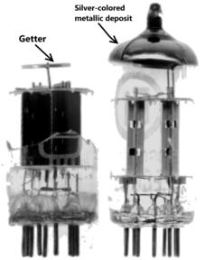
quite easily. Most vacuum tubes are equipped with a
"getter," which is a small reactive piece of metal inside the
tube. When it is heated, some of it it evaporates and combines
with the trace gasses in the tube and deposits them on the glass walls
of the tube. That produces the silvering as shown in the
photo to the left. Some gasses will be absorbed right into
the surface of the getter itself. This restores the vacuum,
and permits the tube to function as it was designed.
When the tube was manufactured, the manufacturer used the getter for
the final scrubbing of the vacuum in the tube. Now, after many
decades, you fire up the tube and find it has some trace gasses causing
grid emission. If you don't have a tube tester, simply install the tube(s) into your radio, turn off the SG switch if it involves the finals (so they can't draw heavy current and pop your cathode resistors) , turn on the heater switch, and let the radio sit for a while. Obviously you don't want to transmit while the getter is doing its job. That's it! Unless you let the radio sit unused for another 30 years, you've successfully restored the vacuum. I can hear my calibrator on both sides of zero beat, even after aligning my carrier frequencies - Is this "blowby" past my IF filters? Probably not. The Kenwoods of this era had great IF response, and the designers were well aware of the need to properly design the circuitry and layout in that all-important selectivity section. What you are most likely hearing is the phenominal gain of the receiver in these hybrids. Keep in mind that the gain of your receiver exceeds 130 db (0.1uv input signal, ~1V output, a gain of at least 10,000,000), and if you have the AGC turned on, all that gain is acting to let you hear any signal as you tune through zero-beat, however tiny! Try this: Turn your AGC off and turn down your RF gain until you see perhaps S-5 on the meter. Now tune through the calibrator signal again and see if you hear anything on the other side of zero beat. Not likely! This represents real world conditions, where you are talking to an S-5 strength station, and you can now see what you will hear of an S-9 station just the other side of zero-beat - Nothing! Pretty darn phenominal! This of course will also be true when you have your AGC on and your RF gain up while receiving a weak station. The AGC takes the place of you riding your RF gain control in the above experiment. You say that the cathode resistors serve double duty as fuses to protect the tubes, transformer, etc. BALONEY! I don't agree! If the cathode resistors are blown, the tubes must be shorted and bad. I repair Kenwoods too, and if the cathode resistors are blown, I replace the tubes AND the cathode resistors! The series circuit of tube, transformer, etc. can't provide enough power to blow the cathode resistors. You are wrong, Ken. You are doing a great injustice to your customers charging them for tubes when only the resistors need to be replaced 99% of the time. You can ask the many hundreds of my customers who have successfully replaced their cathode resistors on my advice after mistuning or misloading their rig, and have now had years of service from their rigs with original finals (and learning to tune more carefully!). The High Voltage power supply in the Kenwoods consists of the transformer, rectifiers, and HV filter caps. The 100uF caps in series provide 50uF of capactance, and the voltage in receive climbs to over 900V, actually about 930V in most rigs. When you key-down, that makes more than 20 joules available to the finals! This can provide Amps of current for a good fraction of second. The 6146B data sheet from RCA show typical plate characteristics through 920ma. For two tubes in parallel, as used in the Kenwoods, that's 1840 ma, or more than 1.8 Amps. Under adverse operating conditions, such as the tank circuit being severely mistuned, or the antenna coax open, it would not be out of the question for over twice that current to flow through the finals! If the instantaneous current hits 4A, that's 80 Watts dissipated in 2W worth of resistors! As those of you who have experienced this phenomena have noted, it can produce quite a "Pop and Flash". The tubes are unharmed, the transformer is unharmed, the caps are unharmed, shucks, just the cathode R's are toast . . . If that's not doing double duty as fuses, I don't know what is! Why are the tubes and power transformer unharmed? Because that brief, short-lived (because the cathode resistors opened!) rush of current through the tubes, they don't have a chance to overheat or be otherwise damaged. Vacuum tubes are very resilient! The power transformer is current-limited by its winding resistance, and would have to be shorted for a relatively long time to overheat. In the fraction of a second it takes for the cathode resistors to blow, the transformer is absolutely unaffected - All the current came from the caps. That is why the line fuse doesn't blow as well. That should tell you something. What about the caps? They are actually most at risk (next to the cathode R's), but since the discharge rate is limited to a few Amps, no damage occurs there either. I've never found a damaged HV cap because of this event occuring. So what's the verdict? The cathode resistors definitely do double duty as fuses to protect the rest of the rig in case of mistuning, disconnected antenna, etc. This is proven in hundreds, perhaps thousands of incidents. When they blow, 99 times out of a 100 nothing else is wrong with the rig - That's why Kenwood placed that size there in the first place. Trust the science and the math, not the occasional loon in the forum who thinks otherwise.
Good question - I have found two reasons for that occurring: The new tubes may have a propensity to arc over. I've found this is true of Chinese tubes in particular. You'll note that the maximum plate voltage for a 6146B is listed as 750V, but we use them at over 900V in out rigs. The old U.S. tubes had no problems at 900V+. Most Chinese 6146B are made for audio output use, and the plate voltage used there is usually below 500V. Sometimes they will arc only one time, and then behave themselves forever. This was probably a stray "hair" of metal burning off. You can replace your cathode R's and try again. If it happens again, it's probably never going away - Get a new tube. The second reason is installing NOS tubes that have become gassy, without cooking them to let the getter do its job restoring a vacuum. See the response a few questions up.
|