|
Instructions for
Assembly
Applies to
TS-530S, TS-830S, VFO-230, VFO-240
Fortunately, all the Kenwood Hybrid remote VFO
cables are wired pin-for-pin. That is, each pin at one end of the
cable connects to the identical pin at the other end of the cable.
Pin 1 connects to Pin 1, Pin 2 connects to Pin 2, etc. The
only pin that has to be closely watched when we assemble the cable is
the shield for the entire cable assembly. The shield must be
connected to pin 7 as shown by the description "bare wire" in Photo 4.
To begin, strip the insulation from both ends of the supplied cable
back about 3/4". This will expose 9 colored wires and the shield
wire. Remove any aluminum shielding foil.
Next, strip about 1/8" of insulation from each of the colored wires,
except the Violet and Grey wires - Cut those off short. They will
not be used. Leave the bare wire full length.
Disassemble the DIN plugs and take one of the pin carriers as
shown in Photo 3. Using a soldering iron with a small tip and
perhaps a "third hand" to assist, solder the bare wire (shield) to
pin 7 as shown in Photo 4. There is no freedom here,
the shield must connect to Pin 7.
NOTE: The orientation in photo 4 is looking
at the "back end" of the connector, where you are soldering the wires
into the solder cups.
DOUBLE NOTE: Be sure
to slide the DIN plug housings onto the cable BEFORE you solder both
connectors on! If you forget, you'll have to unsolder one
connector, slide on the housings, and start over!
I used standard electronic color coding, proceeding clockwise around
the connector.
Black
Brown
Red
Orange
Yellow
Green
Blue
The Violet and Grey leads are cut off - Unused.
It makes no difference what color sequence you use, as long as you use
the identical sequence at the other end!
Once you have all the leads connected,your carrier should look
something like Photo 3. Do the same on the other end of the
cable, being sure that each colored wire goes to the identical pin on
each end.
Reassemble the DIN plugs, and crimp the metal tabs onto the
cable securely. It would be wise to "buzz out" the new
cable, checking pin-for-pin with your ohm-meter, looking for continuity
and shorts.
ENJOY!
|
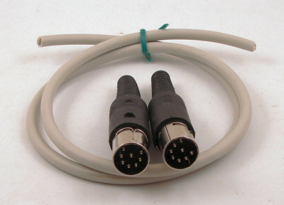
Photo 1
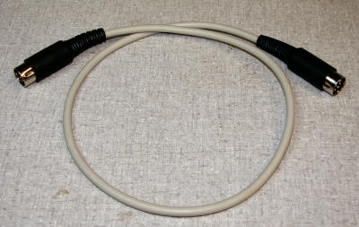
Photo 2
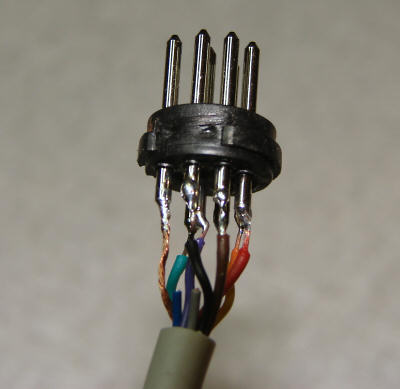
Photo 3
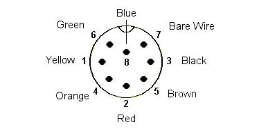
Photo 4 |