| There are many facets to a Kenwwod Hybrid Transceiver. It is virtually impossibe to go through all possible problem areas that might turn up in a page or two, but I've included several common areas that need attention on many rigs. This should help to give you an idea of things to look for if you are performing your own restoration on one of these wonderful Kenwood rigs. I hope you enjoy the photos. 73, Ken, K4EAA |
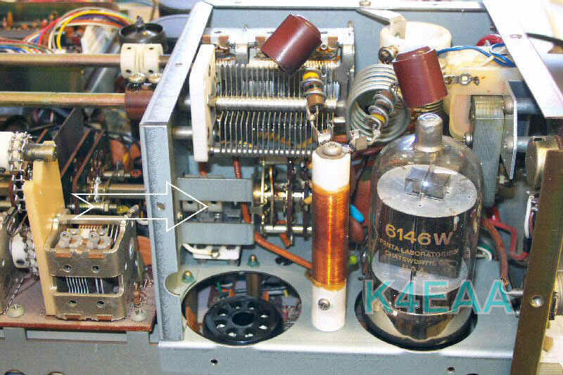
| Soft Bandswitch Operation You have to wiggle the bandswitch to get a
selected band to respond properly. This is most often
caused by a cracked coupler between the front panel control and the
final cage bandswitch. Easy to identify, sort of hard to get
at. It will restore perfect bandswitching if you do,
however.
|
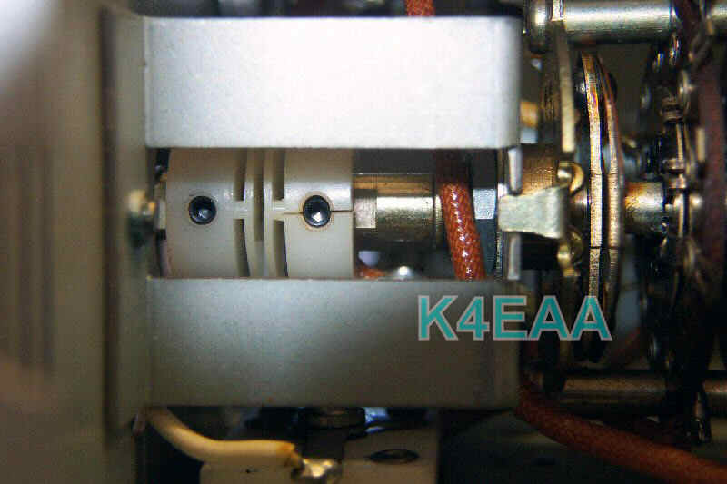
| How do I fix it?
I replace that plastic coupler with a bronze coupler with 4 setscrews
that will last for the next 100 years . . . It's all at ground
potential, no need for an insulator at this juncture . . . Hard
to reach, but well worth the effort. A much closer
view appears in the picture below. |
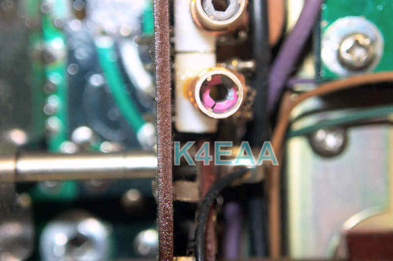
| Cracked
Tuning Cores Even though the Kenwood owner's manuals explicitly warn about using metal tools to try tweaking the tuning cores, some people have to learn for themselves. During an alignment, any time my plastic wand won't budge a core means there's a cracked slug. The slug is nearly impossible to remove without damaging the fragile and brittle coil forms, so I have to stop and change the entire coil. Here's some pictures showing what to watch for: |
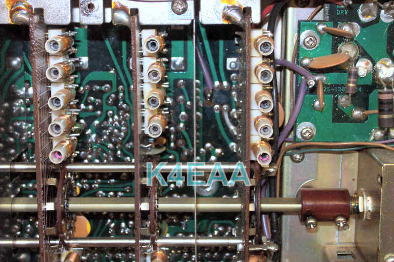
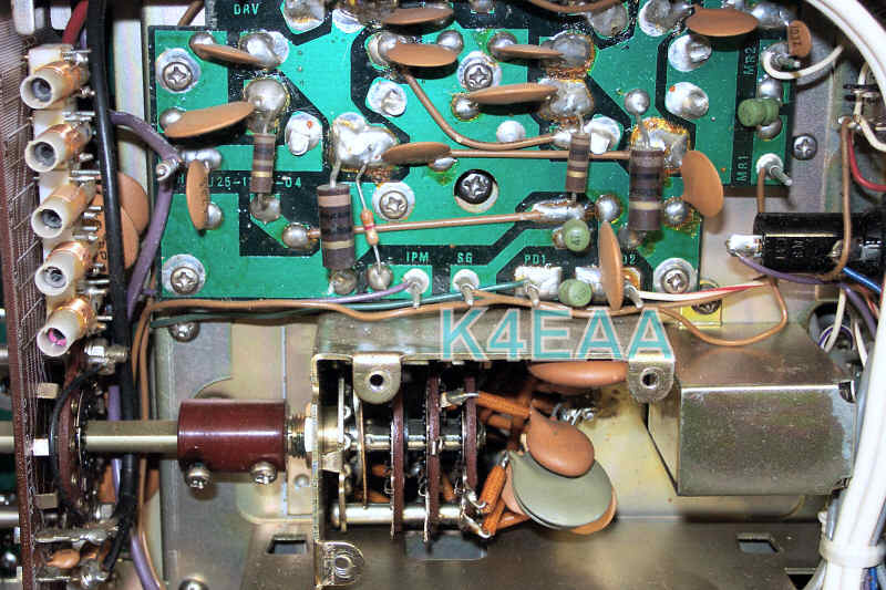
| Damaged Cathode
Resistors If a rig appears to load up properly, with sufficient plate current and good high voltage, but suffers from low output, the answer is many times the cathode resistors. Kenwood uses these resistors as fuses, to protect the finals and power transformer if the rig is mistuned for any length of time. The resistors will overheat, start to climb in resistance, and maybe even burn and rupture. In the picture below, the larger 1W 10 ohm resistors are in series with the cathodes of the 6146B's. In a rig that's been abused, these resistors may look fine, but actually be high in value from being overheated. The only way to tell is to measure them. Being in parallel, they should measure a total 5 ohms to ground. The plate current metering is derived from these R's, and will read much higher than it's actual value if the resistors are damaged. I replace them with 10 ohm 1W metal film units, to maintain the safety that they provide as pseudo-fuses. |
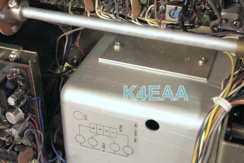
| VFO
Tuning Capacitor Noise & Dropout After 25 to 35 years of use, or certainly after a few years of storage, the VFO capacitor will become noisy, intermittent, even quitting all together because the mechanical sliding contact has tarnished and corroded. The picture below shows the access door on the side of the VFO unit on a 520S. A right angle screwdriver, plenty of light, and a steady hand allow me to remove this cover for access to the sliding contact area on the VFO capacitor. A health dose of contact cleaner, working the cap between its extremes several times, followed by a quality lube applied to the contacts will prepare this important cap for the next 25-35 years. |
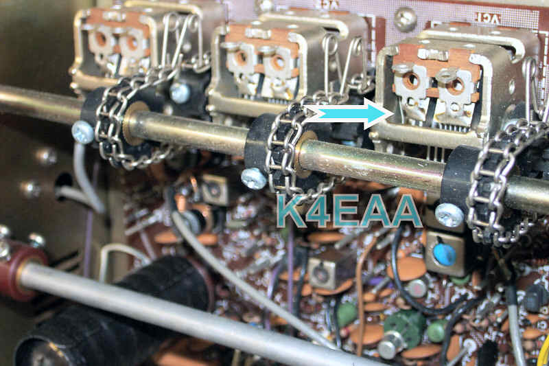
| Don't
Forget those Variable RF Amp, Mixer, and Driver Capacitors Less obvious than the VFO cap, these 3 units for peaking the receiver and driver circuits require cleaning and lubing as well. Each sliding contact must be sprayed and the capacitor worked between its extremes to allow smooth operation and tuning. |
|
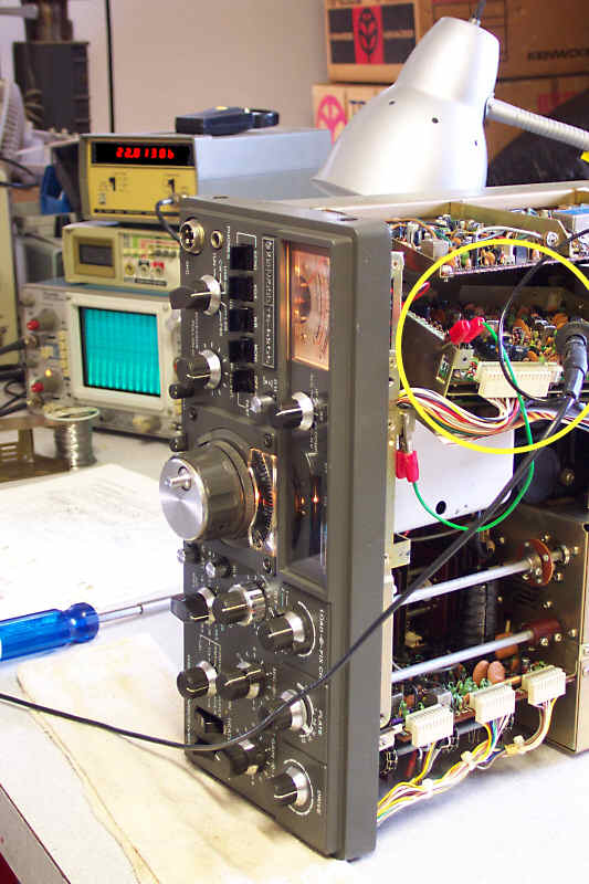
TS-820
DG-1 Access for Repair In this case, the mixer board passes the test, showing strong output and stable frequency on all bands. That means the problem HAS to be on the digital board, which has been known for it's questionable plated through-holes. |
 |
 |
 |
 |
 |
 |
 |