Coupler Replacement On the 530/830 Kenwoods
|
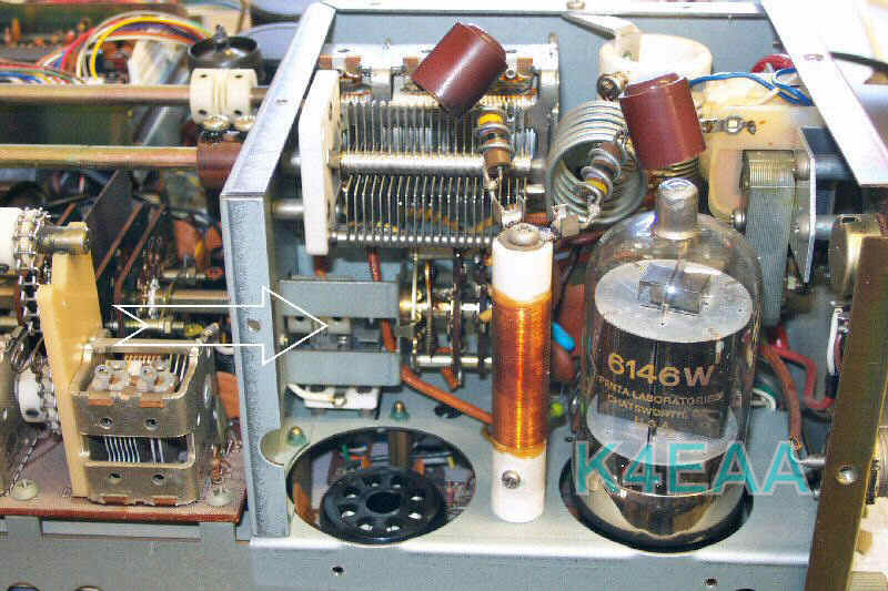
Most of the couplers used on the Kenwood Hybrid rigs are straightforward to replace. The band switch coupler on the 530S's and 830S's is another story. Here's how to do it with the least amount of aggravation. This assumes the use of my "small OD" brass couplers. First of all, please look at the location of the notorious coupler in this photo. |
|
|
In order to access it, you will have to: (1) Remove the top and bottom covers (2) Remove the High Voltage Final Compartment cover (3) Discharge the High Voltage. IMPORTANT! Ground the screw on the top of the RF plate choke to the chassis with an insulated screwdriver, after waiting a few minutes after power-down. (4) Remove the 6146 nearest the front of the radio. This exposes the coupler as shown in the picture. |
|
First place the bandswitch to 1.5MHz, and loosen the setscrews visible in that position using a 1.5mm Allen wrench, preferably one with a longer shaft and a handle This way you can easily reach all the way in there. The 1.5mm Allen wrench also fits the 6-32 setscrews on my couplers. I've found somewhat different hardware on a few Kenwoods, so this is given as a general guideline, but usually accurate. Next, turn the bandswitch to the 10MHz position, and loosen the remaining two setscrews. You should now be able to withdraw the bandswitch shaft, by pulling on the knob from the front of the radio. Only pull it far enough forward to clear the coupler and leave room for its removal. On some Kenwoods, there is enough clearance so you can withdraw the broken coupler by pulling it towards the front of the radio. On others, the driver coils on the RF board will be directly in the way of coupler removal. You might find it impossible to extract the coupler without damaging the mixer coils. The solution is simple - Take your diagonal cutters and cut the coupler into pieces as necessary to extract it. Look for the bridges on the nylon coupler, and simply snip them apart. Once you have the old coupler out, simply slide the new coupler into place and reverse the tightening procedure. My coupler is only 3/8" in diameter, so it will slide over the coils and into position with no removal of the RF board necessary. To verify you are properly indexing the front and rear band switch sections properly, simply make sure you match the original knob position, i.e., be sure the knob pointer is exactly pointing at 10MHz on the band scale as you tighten the setscrews. |
 |
 |
 |
 |
 |
 |
 |