Instructions for
Assembly
Applies
to TS-520, TS-820, TS-520S, TS-820S, VFO-520, VFO-820
Fortunately, all the
Kenwood Hybrid remote VFO cables are wired pin-for-pin. That is,
each pin at one end of the cable connects to the identical pin at the
other end of the cable.
Pin 1 connects to Pin 1, Pin 2 connects to Pin 2, etc. The
only pin that has to be closely watched when we assemble the cable is
the shield for the entire cable assembly. The shield
must be connected to pin 2 as shown by the
description "bare wire" in Diagram 5.
To begin, strip the insulation from both ends of the supplied cable
back 5/8". This will expose 9 colored wires and the shield
wire. Remove any aluminum shielding foil.
Next, strip 1/2" of insulation from each of the colored wires, except
the Grey wire - Cut this one off short. It will
not be used. This leaves 1/8" of insulation on all the other
wires.Leave the bare wire full length. Next, twist and tin the
1/2" of bare strands on each of the wires - This is important, as
assembly is almost impossible if you don't tin these leads.
However, it is very easy if you do tin them. See
photo 3.
Slide the pin carrier over the prepared cable end as shown in photo
3. Using a soldering iron with a small tip and perhaps a
"third hand" to assist, solder the bare wire (shield) to pin 2 as
shown in Photo 4. There is no freedom here, the shield must
connect to Pin 2.
NOTE: The orientation in Diagram 5 is looking at the "pin
end" of the connector, where you are soldering the wires onto the long
pins.
I used standard electronic color coding, proceeding clockwise around
the connector.
Black
Bare Wire (Shield)
Brown
Red
Orange
Yellow
Green
Blue
Violet
The Grey lead is cut off - Unused.
It makes no difference what color sequence you use, as long as you use
the identical sequence at the other end!
Once you have all the leads connected,your carrier should look
something like Photo 4. Do the same on the other end of the
cable, being sure that each colored wire goes to the identical pin on
each end.
Lastly, slide the cover over the pins, and secure it to the pin carrier
with RTV (clear 100% silicone bathroom caulk). This will allow
for disassembly of the connector should a wire ever break.
NOTE: If you're
a bit heavy-handed while soldering, an alligator clip can be used as a
heat sink on the pin solder joints while you solder each wire to the
pin.
ENJOY!
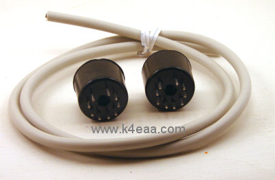
Photo 1 -
Kit Contents
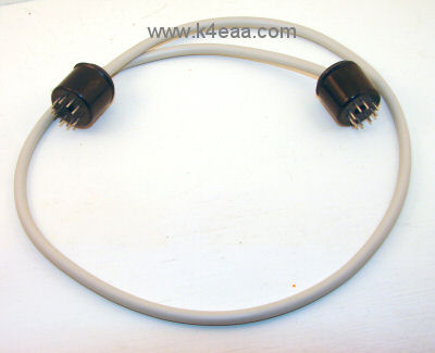
Photo 2 -
Completed cable assembly
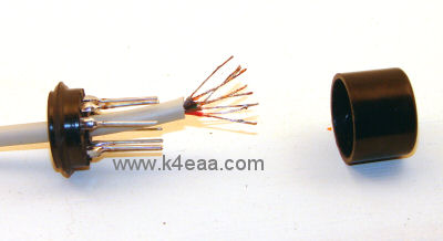
Photo 3 -
Stripping and tinning the leads
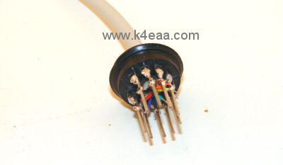
Photo 4 - Leads soldered to pins.
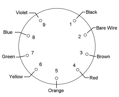
Diagram 5 - Pinout, viewed facing long pins.